S100 Computers

HomeS-100 Boards HistoryNew BoardsSoftwareBoards For Sale
ForumOther Web SitesQuizIndex   
 
An S-100 Console IO Board
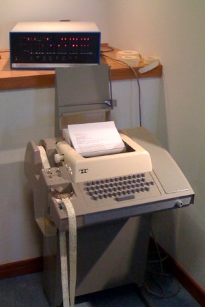
The Altair and other early S-100 computers were envisioned as being connected to a Teletype terminal for data input and output.  A typical setup was as shown here in this picture.  However it was not long until people started to look around for a smaller, simpler and quieter mode of data entry and display.  Don Lancaster's pivotal book "TV Typewriter Cookbook" was instrumental in helping people to put together their own computer CRT terminal using simple common 7400 TTL chips. 
Altair with TTY   Two modes of S100 video display were used. One utilized part of the CPU's 64K memory address space to display text or graphics on a screen. The other simply send ASCII characters to and external CRT terminal like the Lancaster terminal mentioned above or to an S100 board that behaved like an external CRT terminal, that is, it sent video data to an external CRT monitor.

The first of the "in memory" S-100 boards was the Cromemco's TV Dazzler. However this board was best suited for graphics rather than text.  Processor Technologies VDM board or the Solid State Music VDB-1  video boards were very popular early memory mapped video boards.  They allowed decent readable text to be displayed on a CRT monitor.  However the text was limited to 64 characters per line, but they were fast -- even for a 2MHz 8080. Some of the early video games were developed on these boards.  The Sargon chess game with graphics was an early apex of this era.

All this rapidly changed with the introduction of dedicated LSI CRT controller chips.  These specialized microprocessors put on one chip the ability to display text on a CRT monitor utilizing just a few support chips.  This lead to a number of interesting and popular "IO mapped" CRT display boards.  These dominated the S-100 video display board systems in the end.  An excellent example of a board like this was the SD Systems 8024 Video Board. These CRT controller chips are well described in a book by Gerry Kane titled
"CRT Controller Handbook". There were (and still are) four popular CRT controller chips from that era.  Let's look at each briefly:-
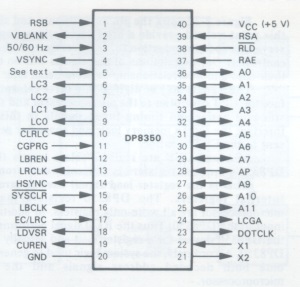
 
The National DP8350
The DP8350 CRT controller series was one of the later CRT controllers to be introduced and provided some functions not available on any of the earlier devices. Nonetheless, its operation was quite straightforward. One reason for its relative simplicity of operation was that some of the functions that were user-programmable in other CRT controllers were mask-programmable in the DP8350s.    

Mask-programming of certain functions made a great deal of sense because, while many functions need to be custom tailored to a particular design, they do not need to be altered once they have been established. The disadvantage of mask-programmable functions is, of course, that you must be a high-volume user of a particular programmed version of the DP8350 in order to justify the cost involved. If you needed only a few devices and one of the standard pre-programmed versions cannot be used, you would not choose the 8350.

That said, the DP8350 series came in three standard ROM versions. These were:-
DP8350 80 characters/row, 24 rows, 7x10 field
DP8352 32 characters/row. 16 rows, 9x12 field
DP8353 80 characters/row, 25 rows, 9x12 field
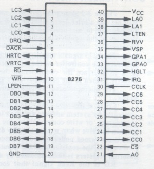
DP8350 Pinout


The Intel  8275
The 8275 CRT controller was an interesting contrast to the
DP8350. The designers of this chip had taken completely different approach to implementing the controller function. While both the DP8350 and 8275 devices allow you to specify many options, such as character size and timing chain parameters, the 8275 options are specified under program control instead of being mask-programmed as in the DP8350. 

The unique feature of the 8275 CRT controller was the inclusion of two
80-character buffers within the device. The presence of these data buffers and the microprocessor interface logic provided by the 8275 imply, and in fact demand, a very specific system configuration — one that is quite different from that which would be used with the DP8350.  The device was usually used with a DMA controller such as a 8257.  The DMA controller generated the screen memory addresses and loaded the data to be displayed into the 8275's "row buffers".
    
The 8275 did not provide any dot timing logic but did generate the lower frequency scan line counter signals and HSYNC and VSYNC timing signals. The cursor logic and blanking logic provided by the 8275 was quite extensive and allows you to easily implement a number of options with a minimum of external circuitry. Light pen logic was also provided by the 8275.
  8275 Pinout
 
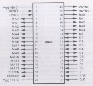
The Motorola 6845
The 6845 CRT controller was somewhere between the DP8350 device
and the 8275 device in its functional organization and capabilities. It was similar to the DP8350 in the way that it was positioned functionally within a system; it coordinates the flow of data from screen memory to character generator logic and thence onto the CRT monitor, but data did not actually pass through the 6845 as was the case with the 8275 device. However, the 6845 was a fully programmable device, like the 8275, instead of being mask-programmable like the DP8350. 
    
The 6845 provided screen memory addressing logic but no memory contention logic. The light pen logic, cursor logic, and scan line counters provided by the 6845 were similar to those of the 8275, although the scrolling and cursor logic was more limited in the 6845. Similarly, the blanking logic provided by the 6845 was minimal, although adequate, and did not provide as many options as the 8275. No dot timing logic was provided on-chip, but  HSYNC/VSYNC generation logic was present on the 6845. The 6845 provided a full complement of programmable registers, there were however no status or control registers or signals provided by the 6845 to simplify the microprocessor interface.
      
The 6845's real claim to fame however was that it was adopted by IBM for the initial IBM-PC's video board. This lead to its wide use and software development and later to further CRT/video chips along the same lines.
  6845 Pinout
 
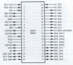
The SMC Microsystems 5027
The 5027 CRT controller was one of the first of the LSI controller
devices introduced. The functions provided by the 5027 may appear to be somewhat more elementary than those available with other above devices. Nonetheless, the 5027 still provided several interesting functions not available on any of the above devices.  For a time it was quite popular and second sourced by the likes of TI (TMS9927), Solid State Scientific and Mostek. If you compare this chip to the other CRT controllers, it may appear that the amount of logic provided by the 5027 is approximately equal to that provided by the other devices. However, when you look in detail at the  5027, many of the functions are implemented in a minimal fashion. For example, cursor logic is provided by the 5027, but the logic provided simply generates a continuous stream of dots at a specified cursor location. You cannot make the cursor automatically blink, nor do you have any options in specifying the shape of the cursor symbol as was the case with the other CRT controllers.  On the other hand, the SYNC generation logic provided by the 5027 exceeds that which is provided by most of the other devices. Not only are HSYNC and VSYNC generated by the device, but a composite sync (CSYNC) signal was also available. The 5027 provides no memory contention logic to simplify access to screen memory by both the microprocessor and the CRT controller. In addition, the screen memory addressing logic provided by the 5027 always addresses screen memory on a row/column basis. It could not generate linear memory addresses.
5027 pinout
 
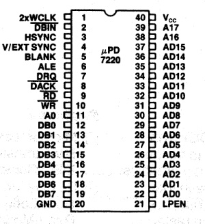
The NEC 7220
The 7220 video controller, (which came out in the early 80's), brought video display graphics to a new level. It was the NVIDEA chip of its day. There were two in NEC's personal computer and it was incorporated into a number of other high end desktop computers such as HP's, DEC and Epson.
The 7220 "Graphics Display Controller" -- as NEC called it, was an intelligent microprocessor peripheral designed to be the
heart of a high performance raster-scan computer graphics and character display system. Positioned between the video display memory and the microprocessor bus, the 7220 performed the tasks needed to generate the raster display and manage the display memory. Processor software overhead was minimized by the 7220's sophisticated instruction set, graphics figure drawing, and DMA transfer capabilities. The display memory supported by the 7220 could be configured in any number of  formats and sizes up to 256K 16-bit words. The display could be zoomed and panned, while partitioned screen areas could be independently scrolled. With its light pen input and multiple controller capability, the 7220 was ideal for advanced computer graphics applications.  Unfortunately it never really caught on mainly because it was ahead of it's time and there was a very steep learning curve to program the chip.  Also its color handling capability was limited.
Nec 7220

What CRT controller should we use?  After a detailed consideration of the above controllers by a number of S-100 users including Andrew Lynch, Michael Petry and Kipp Yeakel, we decided to take an approach that utilized a more modern microprocessor and that had the capability to display a higher level of text resolution than the standard 80X24  of the early 80's.   We all spend many hours these days looking at LCD displays with resolutions past 1600x1200 pixels per display, there is no reason why we should put up with a low resolution S-100 video board.  This will become more apparent when we go to 16 bit CPU systems next year.

The microprocessor we decided upon (two per board actually), was the 32 bit, 8 core Parallax Inc. microprocessor called the Propeller P8X32.
   
 
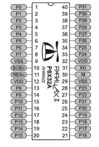
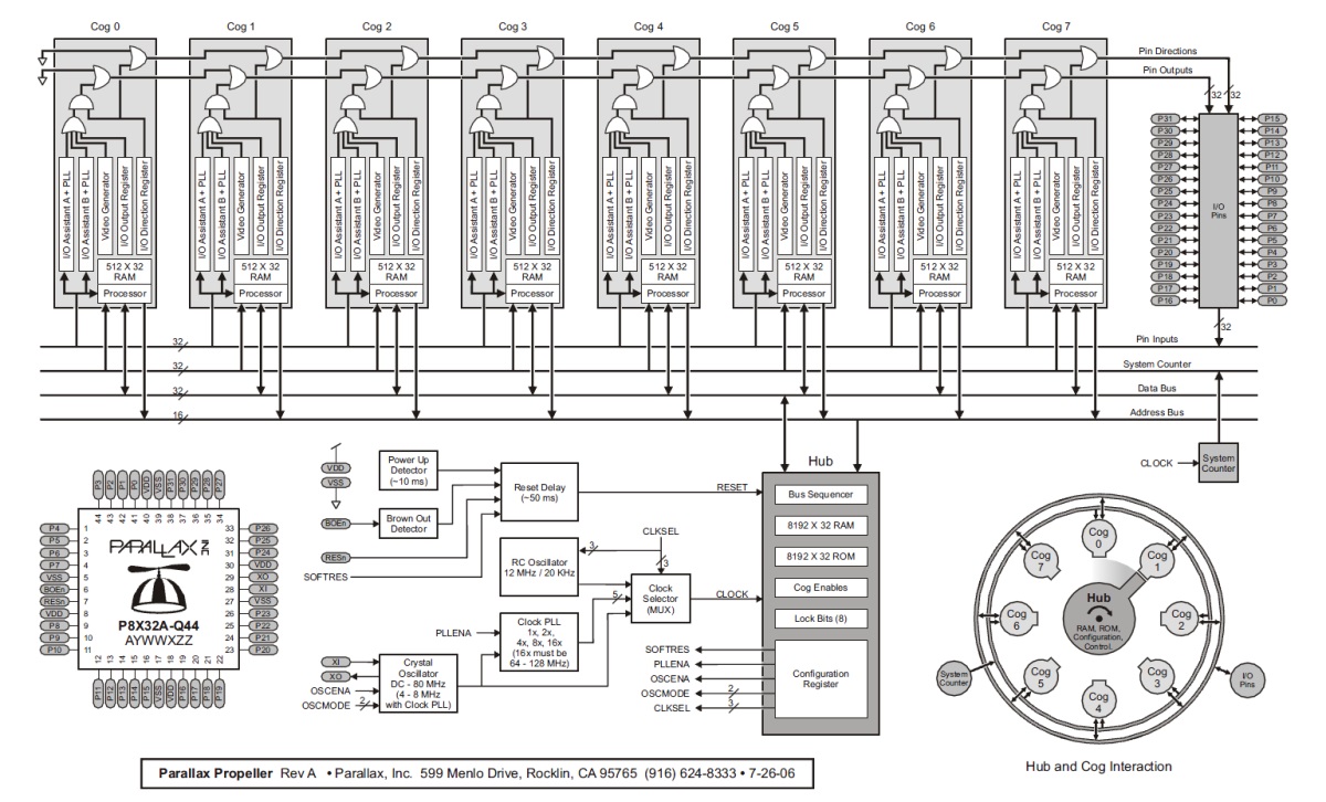
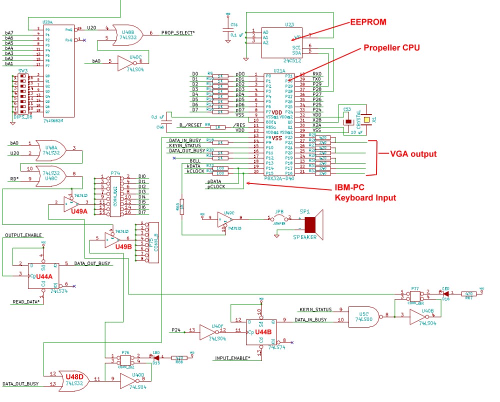
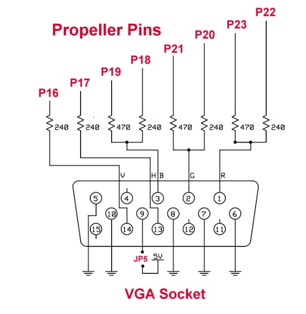
The Propeller P8X32
The Propeller P8X32 chip is a multi-core microcontroller. It has 8 cores, called "Cogs", 32k of shared RAM, 32k of ROM, and 32 I/O pins. The Cogs each have their own local memory, and share access to the 32k Hub memory. They also share access to the 32 I/O pins. They, also, each have their own pair of user configurable counters with PLLs and a Video Generator that aids in driving either NTSC/PAL or VGA video outputs.  There are two types of RAM associated with this chip:-

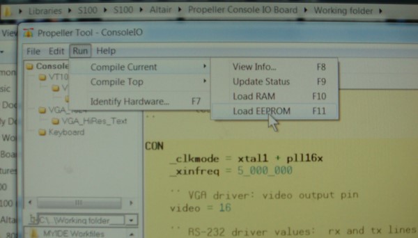
Hub RAM
is the primary memory of the Propeller chip. It is entirely separate from "Cog RAM"" (See below).
A program running in a Cog (whether a user program or the Propeller Spin Interpreter ) has access to the Hub RAM through the use of various word or byte instructions. The design of the Propeller is such that all of these instructions are 'atomic', which means that they will always complete in full, never partially, and if two Cogs do write to the same Hub RAM location, the value placed will be that of the last written. The value placed will never be a mix of what both Cogs attempted to write.  The Hub RAM may be considered to be 32K x 8 bits, 16K x 16 bits, 8K x 32 bits or in any combination as circumstances dictate.

Hub RAM is loaded from an external 32K x 8 bit I2C EEPROM after Reset or is downloaded into it from a PC based Propeller Tool (or other third-party) Propeller Boot loader. Once the Hub RAM has been loaded, a "Spin Interpreter" is loaded into Cog 0 which begins execution of the Spin program which has just been loaded.
 
The external EEPROM and any downloaded program must always contain a Spin program to be executed, even if this is just a small Spin program to place the Propeller in an operating mode other than as a Spin interpreter. 
Propeller
This can be better understood when you realize that the Hub RAM does not contain primary machine code executed by the real processor as in conventional microcontrollers. The Hub RAM contains just - data. The meaning of this data depends on what the real program(s) running in the COG(s) think is appropriate. As COG 0 starts with the SPIN interpreter, it is the master to decide.    Cog RAM is the memory local to each Cog. It consists of 496 longs of general purpose RAM for code and data, and 16 special purpose registers. Memory addresses 0-1EFH can serve as general purpose data storage areas or instructions, addresses 1F0H to 1FFH are special purpose "registers".     BTW, the Propeller does not use interrupts as most other microcontrollers do. All external signaling events must be detected by polling or by waiting for an incoming line to go high or low. With the Propeller's multi-Cog architecture this is not as much of a problem as it would be for a single core processor. With one or more Cogs dedicated to 'interrupt handling', idling until the appropriate signal conditions are met, other Cogs can continue processing unaffected.  It's a different way of doing things. Once you get familiar with it turns out to be very efficient.   
 

Here is the classical diagram Parallax provides of their propeller chip:- 
  
Propeller Diagram
 
The chip actually comes is a 44 pin version and a 40 pin DIP version. We will use the latter.
    

Video Output

Each Cog has its own video generator module that facilitates transmitting video image data at a constant rate. There are two registers (VCFG and VSCL) and one instruction (WAITVID) which provide control and access to the video generator. The timing signal for the Video Generator is provided by Counter A running in a PLL mode (PLLA).  Programming is fairly tricky requiring various registers to have carefully selected values.  Fortunately there are a number of well written code examples available by now.
There is an almost religious following of people supporting this microprocessor. The company Parallax has an outstanding reputation for support and help. Please see their web site for further information or a forum such as the Parallax forum

A Prototype S-100 Consol IO Board

It turns out that the chip overhead to support a Propeller chip on the S-100 bus to send data to a VGA type monitor is relatively simple.  The chip can be setup to take a direct IBM-PC keyboard input (clock and data lines - two pins), send 8 bits of data to the S-100 bus and collect from the S-100 bus 8 bits of data to display on a CRT (VGA like monitor).
With the extra space on the board we added a number of other useful functions.  First we need to have an interface such that the propeller EEPROM can be programmed over a serial/USB port form an external PC or other computer.   This allows you to tweak and optimize any code you write for the chip.  Currently this can be done in two ways. Either using a "classical" RS-232 serial line and three lines Tx, Tx and DTR, or alternatively you can use the specialized Propeller specific "PropPlug". This is a small device that allows you to easily communicate with the Propeller over a USB port. Second we took advantage of the Propellers ability to easily support a microSD Card Interface.  This can act like a CP/M block device (disk) and is a lot like a large floppy disk drive.  It acts as an 8MB, high reliability, low power, fast and completely silent floppy disk drive!  The Propeller  microSD card uses FAT32 as its native file system and the Propeller maps a CP/M block device into a file on the microSD file system.  In effect the microSD card can have multiple disk image files on it and the CP/M BIOS can tell the Propeller to "change disks" to flip between disk images.  All the CP/M BIOS sees at any given instance is the disk image you set as a standard CP/M block device.  What's nice is that in theory the microSD could be popped out, placed into a generic PC, run some software like Michael Haardt's CPM-tools and now the Windows PC can access the CP/M file systems embedded in the disk images stored on the microSD file system. 

We also felt it would be nice to be able to use this board with old ASCII keyboards and with the S100 Keyboard Converter board. The latter has that  advantage it is already setup to translate single key commands (like the F1-F12 keys) into long commonly used ASCII strings for use in CPM, DOS etc.  For this however we did have to add a second Propeller chip. There were simply not enough pins available on a single Propeller.  The two boards communicate with a short over the top ribbon cable. Finally since there was still extra space on the board  we added an Ethernet connection using a PropNIC Ethernet adapter. This "chip" contains an Ethernet Jack, a Microchip ENC28J60 and all requisite parts for a Internet or LAN connection. More on this exciting addition later! Here is an early picture of a partially built prototype Console IO board.  As shown, it just collects keyboard characters and displays then on a VGA monitor.
 
Early Consol IO Board
  
The red mini board is the Micro SD card Adaptor.  Propeller0 is in the center of the board.  Here is an early schematic of this board.  Here is a layout of the board. 


A SECOND PROTOTYPE BOARD
Realizing that we tried to put too much on the above board,  we re-designed the board to a much simpler board using just one Propeller chip, an IBM-PC keyboard input and a VGA style video output.  One thing that became quite apparent with our first board was,  that while the Propeller chip with its 5X16 MHz internal clock frequency was fast, it was not fast enough to keep up to a 10MHz (or slower) Z80 single I/O instruction on the S-100 bus.   In other words the propeller could not in time, recognize (via a status bit) that the S-100 bus/Z80 was sending 8 bits of data on the bus, receive that data, display it in video RAM, reset the status bits  and be back ready for the next S-100 I/O cycle without slamming wait states on the S-100 bus.   This was certainly the case with Spin written code but also so for Propeller driven assembly language code. This second board took all the S-100 bus interface status and signal latching overhead away from the Propeller chip by utilizing a few common 74LSxx chips and thereby allowed the Propeller to concentrate almost 100% on converting ASCII input data into VGA display output.  This eliminated the need for an S-100 wait state requirement.  Here is a picture of this second prototype board:-   
 
V2 Prototype Board 
    
You will immediately notice that besides the "Board Read/Write" LED's there are two pairs of LED Hex displays.   One pair displays the actual IBM-PC keyboard Key pressed code. The second pair display the resulting software converted ASCII key presented to the S-100 bus by the Propeller chip.  This is whole process is explained in more detail in the write-up of our S-100 IBM-PC ASCII converter board.

A detailed schematic of this second prototype board can be obtained here.  Let us look at a few sections.   
    
KeyIN Status
 
 
First the Keyboard Input section:

The board uses only two of the Z80's 256 available I/O ports.  They are set with switches SW2 and SW3.  The test software uses ports 14H-15H.  When the Z80 addresses ports in this range, U20 pin 19 will go low.  U48B pin 6 will go low for data port 15H, U48C pin 8 will go low for status port 14H.

When the Propeller accepts (and translates) a key press character, it will place the ASCII data on its pins 1-8 (P0-P7).   It will latch the data into U47-pin 11 (see below) by pulsing its pin 33 (P24) low. This pulsing of P24 also clocks the 74LS74, U44B, raising "DATA_IN_BUSY" (pin 9) and pin 14 (P9) of the Propeller.  ONLY THEN, does the propeller pulse its pin 15 (P10) high. This line, "KEYIN_STATUS", is combined with DATA_IN_BUSY at U5C and eventually appears as a status bit from U49A pin 3, for the S-100 bus where (in my case) it will appear as a high bit for port 14H.  This indicates to the S-100 bus there is a keyboard character available.  When the S-100 bus reads the data, bringing INPUT_ENABLE* (pin 1 of U47) low,  this also resets the U44B (a 74LS74)  and this resets the 74LS74 (U44B), which lowers DATA_IN_BUSY, which resets the U49B pin 3 status bit.  The Propeller now seeing DATA_IN_BUSY low on its pin 14 (P9) then lowers its pin 15 (P10) setting things up for the next character.

The reason pin 9 of U44B does not go directly to pin 5 of U49B is because the Spin encoded p24 pulse is quite long (in terms of a 10MHz Z80 I/O signals). This leads to the Z80 picking up two sometimes three false characters. By qualifying the DATA_IN_BUSY signal so that only when this signal is high  and KEYIN_STATUS is high (and the data now latched at U47), do we flag the bus that there is a keyboard character available.

Because  pin 3 of U49A can be jumpered to any of the 8 bit data in lines of the S-100 bus, you can configure the keyboard status bit to indicate keyboard data is ready in any way (+/- level, any port, any bit) so the board will splice into any current monitor/BIOS software being used in your system without any software modification.    This is very important as none of us wants to go back are redo all that old software!

The actual ASCII data is latched into U47 using pin 33 (p24) of the Propeller chip. 
 
S100 Interface Circuit
 
This all sounds more complicated than it actually is.   The whole thing can be handled in the following few lines of Propeller Spin code.
     
 Spin key In
      
The Keyboard Output section:
The keyboard output section S-100 handshaking is also handled in 74LSxx hardware leaving the Propeller chip free to concentrate on the fairly complex process of displaying console output data on the VGA display.  

The complication in this case is that the S-100 bus can send a character to the Propeller chip at any time  - even when the Propeller is busy.  We therefore need to latch the data and a status bit any time the S-100 bus deposits a character for display. This is done with U46 (see above) as follows:  When the S-100 Z80 deposits a character for display (by latching it into U46, a 74LS374), with the OUTPUT_ENABLE signal it also clocks the 74LS74, (U44A). This in turn sets DATA_OUT_BUSY which is an input to pin 16 (p11) of the Propeller.  It also sets a bit (U49B, pin 6) that can be read from the S-100 bus on P75 as a Console output busy flag. 

Again the circuit is designed so any port, polarity and bit can be used so the board will splice into any current monitor/BIOS software being used in your system. The propeller (eventually) sees the p11 set. It first outputs on p8 a high that goes to pin 12 of U48D -- in effect holding the input of U49B high. It then inputs the actual ASCII data on U46 by bringing its pin 1 low. This places the data on the Propeller pins 1-8, and eventual displays of the ASCII data on the VGA screen.  P25 going low not only enables the data on to the Propeller pins from (U46), it resets the 74LS74 U44A as well bringing its pin 5 low.  However because p8 is still high the input to u49B does not change.  Only when the Propeller lowers p8 does U49B change thus indicating to the S-100 bus the board is ready to receive another character.  

Again the reason for this "double gating" of the status signal is because  the Spin encoded p25 pulse (READ_DATA*) is quite long (in terms of a 10MHz Z80 I/O signals).  The Spin Propeller clear pulse (p25) is too long to quickly clear the busy signal to the S-100 bus via U44A to prevent characters being dropped when fast data out rates come from the S-100 bus. 

Note, there are other ways this long Spin pulse issue could be solved, in hardware for example, by using edge triggered chips, or a narrow pulse with a 74LS121 chip, or alternatively in software perhaps by using Propeller assembly language code modules.  However since there were many spare pins available on the Propeller chip I chose to use the simplest approach.  Here is the relevant Spin code for character output and display:-
      
Spin key out

 
VGA Display Software.
Because the Propeller chip is now quite disengaged from the whole process of keyboard/S100 bus I/O it can really be tuned to the process of displaying a very high quality VGA display.   There are a few such displays in the public domain. Some with amazing resolution and properties. With 8 cogs available the sky's the limit! I currently have a rudimentary one going for this board (80X24) and would really appreciate help for a display with more lines and more characters/line.  Here is a picture of some basic text using the current software:
 
Second LCD display
 
Programming the Propeller Chip.
Parallax Inc., provides a complete self contained Windows GUI interface to write Spin and assembly code to run the propeller chip. Please see their web site for further information or a forum such as the Parallax forum.  In terms of hardware communication between your Windows PC and the S-100 board you have two choices.  You can use a traditional serial port or you can use a special parallax USB based "PropPlug" adaptor.  There are sockets for both on the board.  I recommend the USB connection. Not only is it faster but it is easier to get working.  The serial connection to a Propeller uses a non standard way or resetting the chip using the RS232 DTR line.    The Propeller chip, EEPROM and PropPlug can be obtained from many suppliers. For example Jameco, (#2007134 and #74843, #2109368).
PropPlug


The Final Console IO Board
Finally after much trial and error we arrived at the following "Commercial Quality" S-100 Console IO board:-

Final Console IO Board
The board is essentially the same as the second prototype described above except  U47 was changed from a 74LS373 to a 74LS374 (i.e. latching the data output).  The  layout of the board is relatively straightforward and the circuitry is simpler than some of our previous boards.  Here are the main features:-
 
Board layout

 
Building the Board - Step by Step Instructions.

First inspect the board for scratches or cut traces.   Insert all IC sockets, Caps, resistors,  resistor networks, the voltage regulator and jumper pins.  Take care to get the polarity of caps correct. The square pad is the positive side.    Do not insert the 4 LED yet. Please note there are two changes to the schematic for this board (see below). As mentioned above, U47 should be a 74LS374 (not an 74LS373) and the resistor R68 should be 100K and not 1K.  Be sure and insert the three transistors in their correct orientation.  The 2N3904's have their flat side facing down, the 2N3906 has it facing up.

Transistors

Test the empty board for +5 volts on all the empty IC sockets. Test that pin 12 of U12 and pin 8 of U23 is 3.3 Volts.
We will now test the I/O port addressing of the board. While my monitor/CPM BIOS expects to find the Console I/O ports at 0 & 1H, for testing purposes we will have the status port at 14H and the data port at 15H.  This way you can use your normal video board while testing this board.  The two dip switches should be configured like this:-

Switches

Install jumpers K5 1-2, K1 2-3. P78 1-2 3-4. Remember that jumpers are numbered vertically.   Install U20, U3, U48, U40, U5, U6, U14 and  U12.   
Install the board in your S-100 system (using an extender board) and from your monitor place the following code at 0H in RAM

DB  15  C3 00 00

Check with a logic probe that IC socket U47 pin 1 pulses low continuously
Then place the following code in RAM at 0H

D3 15  C3 00 00

Check with a logic probe that IC socket U46 pin 11 pulses low continuously as shown here:-

Port Addressing

If both of the above tests check out add U46 and U47 (both 74LS374's).   Next add U35 (a 74LS123) and insert the LED's D3 and D4. Check they are working and orientated correctly by repeating the above tests before soldering them in.  Choose the colors you want yourself. I use blue LED's on all my boards for "board select".

Next add U49 (a 74LS125). Install jumpers P77 1-3 & 2-4 and a P74 jumper for the status bit you will use for your keyboard status in routine. That input bit should read low.    Temporally tie U5 pin 10 to ground. The input port 14H should change to FFH.  Insert a (RED) LED, D16, test and solder.  Remove the U5 jumper.

Next install jumpers P76 1-3 & 2-4 and a P75 jumper for the status bit you will use for your keyboard status out routine. From your monitor input port 14H (console out status). You should get FFH.   Insert a (GREEN) LED, D15 test and solder. Then temporally tie U48 pins 12 & 13 to ground. Inputting port 14H should give 11111001 (if you are using bit 1 & 2 for status bits).  Remove the U48 jumpers.

Next install U44 (a 74LS74).  Power up. The green LED 15 should be on.  It should look like this:-
Temporally touch U5 pin 9 to ground. The red LED D16 should flash.

With this you now have the board correctly addressing the S-100 bus ports.  Next add the TIL HEX displays. First add one and test, (they are expensive). Then all four. They should come up as shown below.

Hex Display Added

We now are ready to configure the board's Console IN and Console OUT status bits.  This is where things are different depending on the exact status bits you are currently using in your own S-100 system.  Different S-100 boards/manufactures used different arrangements.   In general as best I can tell most use the lower of two ports as the status port and the next higher port as the actual data port.  If for some reason your system has it the other way around the jumper P78 will take care of it (see and study the schematic below).  I will use the SD Systems 8024 video board as an example here.  If you look at their manual they have the following code for system keyboard data input:-

INPUT:    IN    A,(00H)        ;Read keyboard status
          AND   02H
          JP    Z,INPUT        ;Loop if not ready       
          IN    A,(01H)        ;Get keyboard data


We see here that the hardware is utilizing bit 1 as a status bit and that if a keyboard character is waiting that bit will go from 0 to 1.  In order to do the same thing on our Console IO board then we will jumper P77 1-4 & 3-2  AND P74 3-4.  If for example your hardware used a different bit you would use a different jumper on P74.  If your hardware use a 0 as a character ready flag,  you would jumper P77 1-3 & 2-4.

Likewise there are times the SD Systems video board is busy updating the video display and is not ready for a new character. The code is as follows:-

OUTPUT:   IN    A,(00H)        ;Read keyboard status
          AND   04H
          JP    Z,OUTPUT       ;Loop if busy
          LD    A,C
          OUT   A,(01H)        ;Output character to console


In this case we have to look at bit 3. If it is a 0, the SD Systems board is busy.  To reproduce the same setup on our Console IO board we jumper P76 1-4 & 2-4 AND P75 to the center row of P74 with 3-6. Remember the center row of pins of P74 go directly to the S-100 data bus, so whatever pin is connected to that row will be the corresponding data bit. The 74LS125 output to these pins is only activated when you input from port 14H (in this test case). This all may sound a little confusing for some initially. So study the schematic (below).  If later you find your display is dropping display characters it is probably because you do not have the status port setup correctly.  Here is a close-up picture of the above setup.

Status Jumpers

The above arrangement allows for a very convenient and flexible arrangement. By configuring the jumpers correctly you should be able to splice this Console IO board into almost any S-100 system and not have to change any of your software.

Next we will add the Propeller CPU (U21) itself and the supporting EEPROM (U25).  Note the crystal is 5MHz.

You then need to construct a VGA ribbon cable connector and connect it carefully to socket X2 (VGAF).

VGA Cable

Be sure you insulate all wires and check the pins on the VGA socket exactly match the corresponding pins on the X2 socket.  When done the pin connections coming from P16 - P22 of the Propeller CPU (pins 21-28), should via the ribbon cable connect to the VGA socket as shown below:-

VGA Socket

If in doubt, remove the Propeller CPU and check that the connections as above in the diagram. The jumper JP5 is not normally needed with modern LCD/CRT displays.

Next we need to do the same thing for the keyboard connection (connector P38).  Fortunately this one is a little easier. The propeller needs only two keyboard signal lines (clock & data) going to its pins 19 & 20 (P14,p15).  Now in a perfect world the pins you take from your PS2 keyboard socket at the back of your S-100 box should line up perfectly with the corresponding ribbon cable pins on P38, however in most cases (an in my case also) no such luck.   To take care of this there is an intermediate jumper P57.  Be sure and get the +5 volts and ground correct to drive power to the keyboard itself.

There are actually two types of sockets used for these IBM type keyboards (not counting the newer USB port driven ones). The original socket was the larger AT style socket shown below.  The much more common socket today, is the PS/2 style socket. (Perhaps the only contribution/residual of the ill famed IBM PS/2 computer). The pinouts are different. The view shown is that of looking into the male socket of the keyboard cable itself.

  Socket AT   Socket PS2

Again if in doubt, remove the Propeller CPU and with a meter check the connections with the ribbon cable attached to the P38 socket.   If you are using the IBM-Keyboard S-100 connector board the jumpers at P57 are: 1-2, 3-4, 5-6, 7-10 & 9-8. 

Do not go further until you are convinced you have the keyboard and VGA connections correct. You probably won't do any damage to the board, VGA display or keyboard but you will save yourself a lot of time later if these connections are incorrect.

You can also add the "buzzer" at this stage. I use a Jameco unit #138713.  However because we are pulling the Propeller P13 signal high to activate, (otherewise the buzzer is on until the Propeller initilizes), the "+" side of the buzzer should go to the round solder pad (not the square one).  In othere words the "+" side of the buzzer should be on the right hand side of the board.  Also remember R68 is 100K (not 1K). 
 
Buzzer
 
Finally we need some way of programming the boards EEPROM (U23).   As I said above, there are two ways of doing this, either over a serial port or via the Parallax PropPlug USB connector.   Both methods work the same with the Parallax software. If you do wish to use the serial connection you must connect P36 to P61 by jumpering P60-1 to P61-1, P60-2 to P61-2, P60-3 to P61-3 and P60-4 to P61-4.  The actual serial connection to your PC is from P36.  See the schematic below for pin connections.

If you use the USB based PropPlug, only P61 is used. Since the socket connections are right angled and facing up, the PropPlug is place in the FRONT row of pins (P61) as shown below.

PropPlug Connection

The Propeller "Spin" program (see below) can be downloaded to the onboard EEPROM (U23) using the Parallax Windows GUI interface. The GUI can be downloaded from here

Upload

You can quickly test the board by outputting 33H to port 15H.  The letter "3" should appear on the top left hand corner of the LCD display.
Likewise if you hit a keyboard key. Inputting from port 15H should give the ASCII code for that key.  I have written a small S-100 diagnostic test program to check out the board's handshaking.  No characters should be dropped.  It is included in the software download at the bottom of this page.
 
Once you are convinced the board is functioning correctly you can switch the I/O port to that of your current Console IO board, remove that board, and use the new board in it's place.

Because the complete source code is available you can configure the graphic display any way you like. I happen to like green text on a black background as can be seen below. However to get a good intensity of green, the resistors R25,R27,R29 should be lowered to about 240 ohms. To set the color/background you want, alter the value in "setColor()" at the start of the VGA_1024.spin module.  Also remember in the Parallax GUI, after you recompile that module to always load the EEPROM with the "Console-IO.spin"  which will pull in the lower modules.  Compiling and loading VGA_1024.spin alone into the EEPROM will not work.

  B-W Text   Green text
  
The important point however is that this text appeared without any changes what so ever being made to my CPM3 BIOS.  All software written for my old video board should work unmodified.   Utilizing this board simplifies my S-100 system. Until now, I needed a separate board to convert the IBM-PC keyboard to a parallel port ASCII format, a separate S-100 video board (an SD Systems 8024) and another board to convert the video output from the video board to a VGA format suitable for a modern LCD display.


Here is a short video demonstrating this board in action and a brief display of some of the Consol-IO's features:-


Calling All Propeller Programmers.
The Spin/Propeller Assembly language modules I have here are quite simple and display 80X25  characters on a display.   This is in a simple VT-100 format. The VT-100 modules were suggested by Michael Petry - thanks Mike. The Propeller chip is capable of displaying a far greater resolution than this.   There are examples out there of 128 characters/line using this chip.  The chip can also utilize a faster clock. However currently I have very little experience programming the Propeller.  What is needed, is somebody to write more optimized code for the board.  The Propeller's 8 cogs have nothing else to do other than just putting up a high resolution VGA display.  There is a dire need here for a good Propeller programmer!  If you can improve the output please let me know I will be delighted to place it here for others to appreciate and utilize.

One other minor point. The boards HEX display is setup to show the input IBM keyboard "scan code" and the resulting translated ASCII code.  Again, I do not know enough Propeller assembly language to know how to display the keyboard scan code in the first pair of HEX displays.  If you solve this problem please let me know. The information is buried somewhere there in the Parallax supplied assembly source code.


Obtaining a Bare Console IO board
Andrew and I are now still have a few commercial quality boards, If you think you will later need a board like this please let Andrew Lynch at N8VEM (see here) know so he can put you on the list for the next "batch" of production boards.
 
Source of chips
Most of the IC's use on this board are common 74LSxx chips available from numerous sources such a Jameco, Mouser & DigiKey -- including the Propeller CPU, EEPROM and PropPlug.  The Propeller crystal is 5MHz. Personally I get most of my stuff from Jameco. If you are on the west coast they have a 1 day delivery. 

The TIL 311A's are expensive (~$20 each from places like Jameco).  However overseas outfits like Utsource sell them in small quantities for ~$5 each. Utsource have about a 1 week delivery time to the US since they use DHL.  It is indeed frustrating these LED HEX displays are so expensive. With the exception of the even rarer HP-5082's other such displays display only the digits 0-9.  An alternative approach would be to use a 7 segment LED decoder such as a DM9368 and a simple 7 segment LED display. However these too are no longer normally stocked.  Normal single line flat panel LCD displays just do not show up well when the card is in the S-100 bus card cage.
 
The links below will contain the most recent schematic of this board.
Note, it may change over time and some IC part or pin numbers may not correlate exactly with the text in the article above.

MOST CURRENT CONSOLE IO BOARD SCHEMATIC  (V3, 5/26/2011)
MOST CURRENT CONSOLE IO BOARD LAYOUT  (V3, 5/26/2011)
MOST CURRENT CONSOLE IO BOARD SOFTWARE  (V3, 5/26/2011)

Other pages describing my S-100 hardware and software.
Please click here to continue...


This page was last modified on 09/18/2011